MOSCOW BAUMANN STATE TECHNICAL UNIVERSITY
DEMO VERSION!!!

BACK

AIM OF THE WORK

EQUIPMENT

   Spectrometer

   Optical behch design

   CCD-detector

   Microprocessor board

   Optical resolution

   Stray Light and Second Order Effects

   Fibre optic cable

   Light passing through fibre

   Fibre design

   Optical fibre types

   Collimating lens

   Objects of research

   AVALight lamp

   Halogen and deuterium lamps

SPECTROMETER CONTROL PARAMETERS

   Integration time

   Average

   Saturation detection levels

   Smoothing

   Correct for dynamic dark

EXPERIMENT

   Experiment scheme

   Àcquaintance with control interfaces

   Order of carrying out the work

   Stage 1

   Stage 2

   Stage 3

   Practical part
 
Light passing through fibre
At passing of light ray on transparent medium with the different values of transmission density (n1 > n2) there are phenomena of reflection and refraction of light.

The refractive index n of medium is name the relation of velocity of light in a vacuum to velocity of light in this medium. Refractive index for every homogeneous material or substance is constant. For silica there is an refractive index about 1,5.


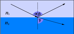
In passage of ray from an medium with a greater transmission density in a medium with a less transmission density (n1 > n2) the corner of refraction will exceed the light incidence angle (γ > α ). Due to the increase of light incidence angle α it is possible to reach the effect of total internal reflection, when light will not pass the boundary of mediums (γ≥90°), based on basis principle of light transmission through optical fibre. Light incidence angle, on which an effect of total internal reflection there is, named the critical angle of light input in optical fibre.


Consequently, in order that a ray propagate only in the limited medium it is necessary :
  • to enter a ray with angle no more than critical angle,
  • to use for the light transmission two mediums with a different transmission densities (refractive index ).


  • For this reason optical fibre consists of core with transmission density more than claddinng transmission density.

    The maximum permissible angle of light input in fibre named acceptance angle, the sine of this angla often reported as a numerical aperture, which is calculated on a formula:
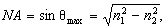
, where θmax - is the acceptance angle, n1 - is an core refractive index, n2 - is an refractive index of the fibre cladding.