|
The use of fiber optics as light guidance allows a great modularity and flexibility in the setup of an optical measurement system. Optical fibers can be made of many materials, such as plastic, glasses and silicates (SiCb). For high quality fiber optics, as used in spectroscopic applications, synthetic fused silica (amorphous silicon dioxide) is used, that can be intentionally doped with trace elements to adjust the optical properties of the glass. 
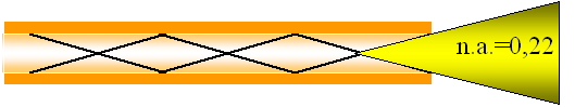
The basic principle of light transport through an optical fiber is total internal reflection. This means that the light within the numerical aperture of a fiber (NA = input acceptance cone) will be reflected and transported through the fiber. The size of the numerical aperture depends on the materials used for core and cladding.
| Technical Data |
| Fiber type |
Step index
|
| Core Numerical Aperture |
0.22 ± 0.02 |
| Buffer NA |
Polyimide (1,78) strips cladding modes |
| Laser damage resistant core |
1,3 kW/mm2CW at 1060nm, up to 10 J, pulsed |
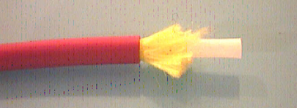
| Sleeve material |
Kevlar reinforced PVC |
| Inner Tubing |
Polypropylene |
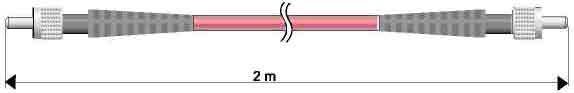
| Outer dimensions |
3.8 mm |
| Temperature Range |
-20 °C to +65 °C |
|
|
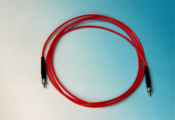
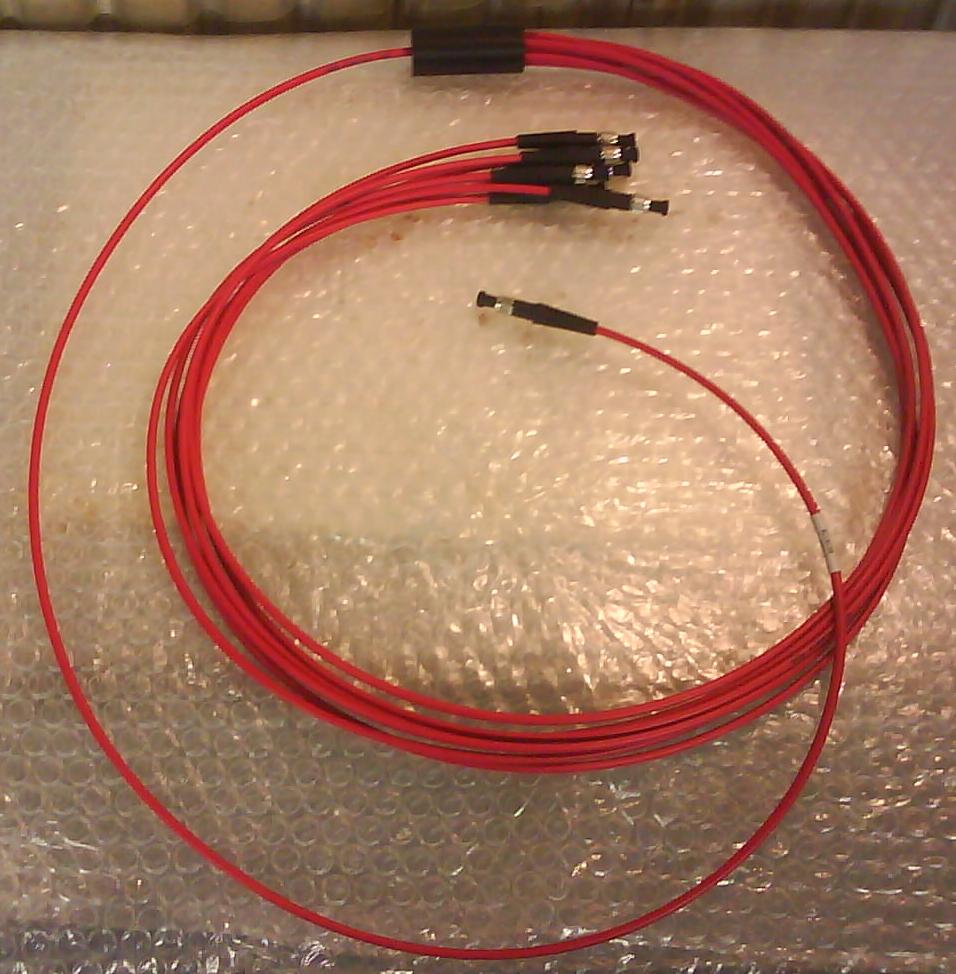
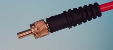
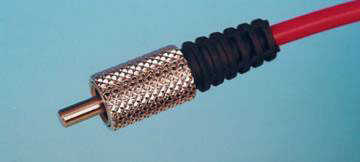
Standard SMA connectors
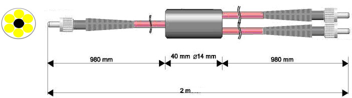
For connecting spectrometers and light sources is used standard fiber optic cables with SMA 905 connectors. The typical insertion loss for the connectors is 0.5 dB. The maximum filling diameter for bundles is 2.46 mm.
|